Propulsion
Core idea
Convert stored potential energy into kinetic energy.
Momentum Exchange / Thrust
Gas enters a nozzle and then gets ejected out with a certain velocity.
The specific impulse is a function of the engine geometry and fuel properties.
for complex molecules (like
| Symbol | Description | Common Units |
|---|---|---|
| Specific Impulse | ||
| Universal Gas Constant | ||
| Combustion Chamber Temperature | ||
| Molecular Weight (Molar Mass) | ||
| Ratio of Specific Heats ( |
Unitless | |
| Nozzle Exit Pressure | ||
| Chamber Pressure | ||
| Ambient (Atmospheric) Pressure | ||
| Propellant Mass Flow Rate | ||
| Nozzle Exit Area |
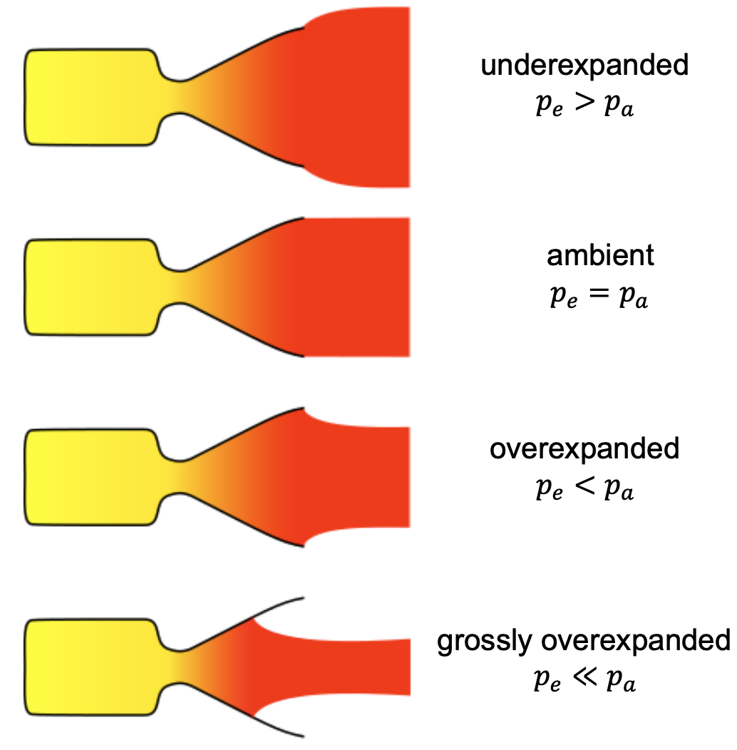
The Nozzle size is depended on the exit pressure and the ambient pressure
Energy Source
Cold gas thrusters
Gas that is released from a pressurized supply through a nozzle without igniting anything.
- Advantages:
- simple
- no thermal signature
- very low electricity/power requirement
- safe components
- Disadvantages:
- very limited maximum thrust
- thrust level dependent on pressure in tank
| Cold Gas | Molecular weight M (u) | Theoretical |
Density (g/cm³) |
|---|---|---|---|
| H₂ | 2.0 | 296 | 0.02 |
| He | 4.0 | 179 | 0.04 |
| Ne | 20.2 | 82 | 0.19 |
| N₂ | 28.0 | 80 | 0.28 |
| Ar | 40.0 | 57 | 0.44 |
| Kr | 83.8 | 39 | 1.08 |
| Xe | 131.3 | 31 | 2.74 |
| CCl₂F₂ (Freon-12) | 120.9 | 46 | Liquid |
| CF₄ | 88.0 | 55 | 0.96 |
| CH₄ | 16.0 | 114 | 0.19 |
| NH₃ | 17.0 | 105 | Liquid |
| N₂O | 44.0 | 67 | Liquid |
Monopropellant
A single propellant decomposes exothermally, typically in presence of a catalyst. This uses the chemical energy stored in the propellant.
- Advantages:
- higher Isp than cold gas
- Disadvantages:
- increased complexity
- difficult components
- lifetime limited by catalyst degradation
Often used propellant is Hydazine:
- versatile
- toxic
- high freezing point
- Isp ~230s (medium)
Bipropellant
Fuel and oxidizer are brought together and then ignited. Fuel and oxidizer can both be stored either as solid or as liquids.
Much higher Isp can be reached compared to monopropellant with both liquid phases, or the complexity can be reduced with solids.
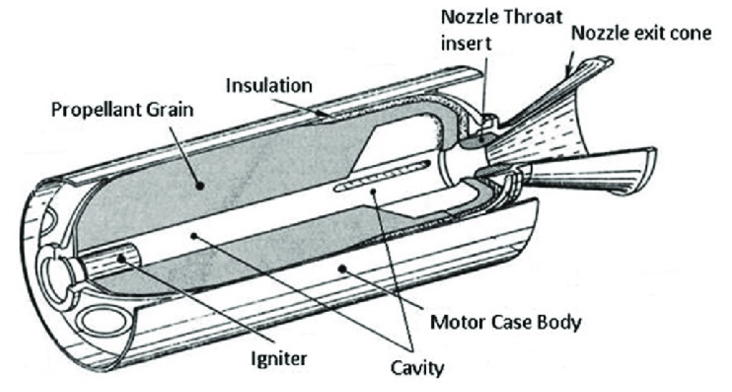
Solid
- Advantages:
- simple design
- high thrust
- long-term storable
- thrust curve can be adapted before launch
- Disadvantages:
- Thrust curve can only be adapted before launch
- all but impossible to stop or restart
- typically toxic
Hybrid propellant system
Combines solid fuel with liquid oxidizer. Widely used for student projects and sounding rockets.
- Advantages over solid:
- higher Isp
- lower explosion hazard
- controllable thrust
- Disadvantages:
- higher complexity
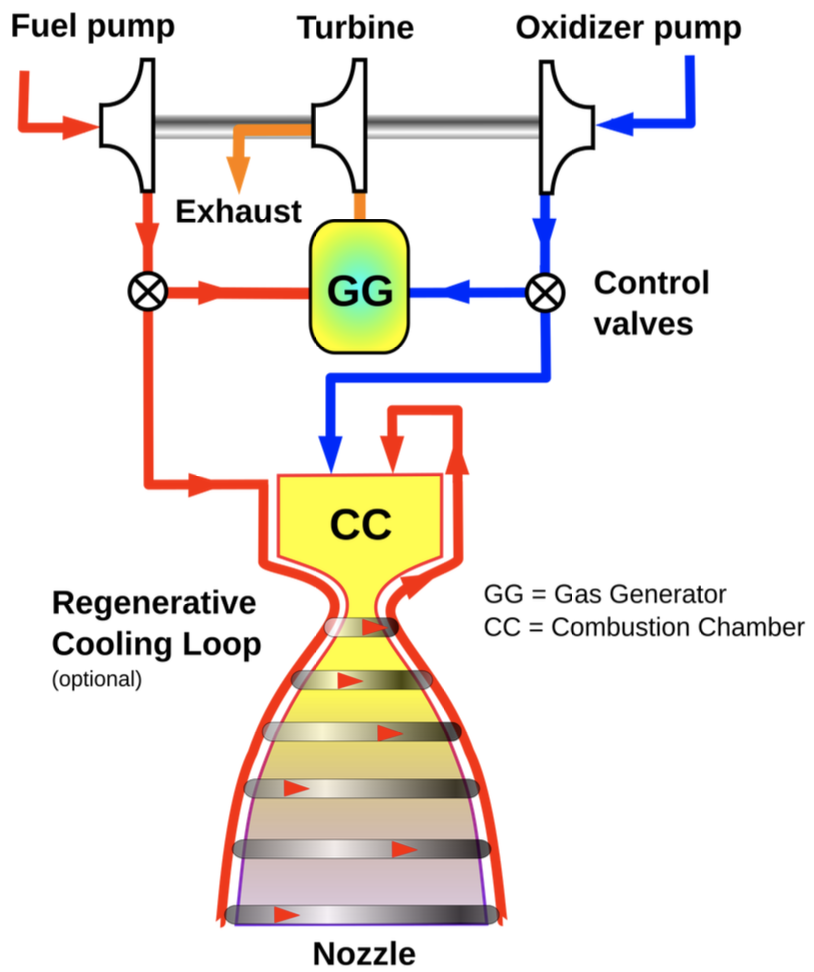
(Bi-) Liquid
Both fuel and oxidizer are in liquid form
- Advantages:
- thrust control and optimal burn rate
- scales to the largest systems
- highest Isp
- refueling and static test burning is possible
- re-usable
- Disadvantages:
- most complex plumbing
- mixture ratio needs to be controlled
- fuels move (slosh)
- cryogenic storage of oxidizer necessary
- significant preparation before launch necessary
Electric Propulsion
| System type | Propulsion principle | Typical propellant | Thrust range | Specific impulse ( |
Typical missions / users | Flight heritage / comments |
|---|---|---|---|---|---|---|
| Resistojet thrusters | Electrically heats a stored neutral gas before expansion in nozzle | N₂, NH₃, H₂O, etc. | 1 – 100 mN | 150 – 400 s | Small-sats, ISS reboost systems, CubeSats | Simple, low-Isp but compact; often first EP step for small platforms |
| Arcjets | DC arc discharge superheats propellant -> nozzle expansion | Hydrazine, NH₃, H₂ | 0.1 – 2 N | 400 – 1,000 s | GEO station-keeping (in 1990s–2000s) | Mature but mostly replaced by Hall / ion systems; higher power demand |
| Hall-effect thrusters (HET) | E×B field traps electrons -> ionize propellant -> ions accelerated by electric field | Xenon (increasingly Krypton or Argon) | 10 – 400 mN | 1,000 – 2,500 s | GEO comsats, LEO constellations (e.g. Starlink, OneWeb), deep-space (BepiColombo, DART) | Most widely used EP today; robust, efficient (~50–65%), 1000s of units in orbit |
| Gridded ion engines (GIE) | Ion extraction through electrostatic grids; separate neutralizer | Xenon | 1 – 250 mN | 2,000 – 10,000 s | Deep-space probes (Deep Space 1, Dawn, Hayabusa 2, BepiColombo), station-keeping | High Isp champion, lower thrust density, long heritage since 1960s |
| Colloid / electrospray thrusters | Charged liquid droplets or ions electrostatically accelerated | Ionic liquid (EMI-BF₄, etc.) | 500 – 3,000 s | Precision attitude and drag-free missions (LISA Pathfinder, GRACE-FO) | Used for micro- and nano-satellites requiring ultra-fine thrust | |
| Field-Emission Electric Propulsion (FEEP) | Field-emission of metal ions from sharp tips | Indium, Cesium | 5,000 – 10,000 s | Attitude control for small, drag-free or formation-flying missions | High precision, low thrust, niche use | |
| Pulsed Plasma Thrusters (PPT) | Electric discharge ablates solid Teflon -> plasma pulse | PTFE (Teflon) | 600 – 1,200 s | Small spacecraft, early microsats, CubeSats | Oldest EP tech (since 1960s); simple, rugged, low efficiency |
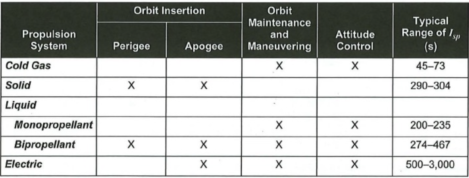
Overview of Propulsion Families
Interaction with other Subsystems
Control Subsystem (ADCS)
- Requirement on propulsion capabilities to maintain attitude
- Requirement on structure tu support weight of propulsion system on ground
- Requirement to tolerate loads from propulsion
- For electric propulsion: Provide power for thrusters
- Tradeoff between attitude control and solar power generation
- Placement of solar panels w.r.t thrusters (plume keep-out-zone)
- Thermal loads from thruster operations
- Indirect effect from attitude control
Plume Effects and Contamination
Depending on fuel combination, the rocket plume will be toxic. Residuals can impinge on solar arrays and sensors. Best practice is to have a 60° half angle keep out zone.